We teased last year that we are working on a new Z-Wave antenna/controller/stick prototype at Nabu Casa. I finally have some up to date prototypes in my hands that I use to work on our firmware.
Our main focus during the development of this device is making sure it has the best range, far above anything that’s currently available to buy. You should really not need a repeater with that controller, but why not try to enable the use case if someone actually does?
…turns out that this is harder than we thought!
Two different kinds of bootloaders
On embedded devices, the bootloader is the first piece of software that starts. It’s responsible for starting the application (here: Z-Wave controller firmware) and may contain additional functionality like updating the application firmware.
For Z-Wave devices, two different kinds of bootloaders exist:
The OTW (over-the-wire) bootloader, also called standalone bootloader, which is used by controllers. The bootloader only stores a single application image.

Uploading a new image is done through the bootloader, which immediately overwrites the current application in place. If this process fails, the application won’t start, and a new image has to be uploaded to recover.
 Because controllers are connected to a host computer the entire time, this isn’t a problem.
The OTA (over-the-air) bootloader, also called application bootloader, which is used by end devices. There are two storage slots for the application, one contains the current image, one contains the new image to be updated.

Uploading a new image is done over the air using the Firmware Update Command Class, and not through the bootloader. Once the upload is done, the application instructs the bootloader to switch to the new image. The booloader then copies the new image over the old one. If the upload process fails, nothing happens and the current application keeps running.

Here we run into the first problem. We need the OTW bootloader for the normal operation of our controller, so we somehow need to make end device firmwares work with it. This actually just works, but we need to disable OTA firmware update functionality, because there is no second storage slot to save the image, and our bootloader wouldn’t know what to do with it.
Switching firmwares
Ideally, switching between controller and end device firmwares should be as easy as upgrading the controller firmware. Select an update file, confirm, and wait for the process to finish. Surprisingly, this also just works, and what was once a Z-Wave controller, is now a repeater a few seconds later. Now, this is where the real fun begins - otherwise I wouldn’t be writing this post.
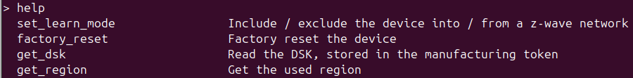
The sample applications in Simplicity SDK, which we build our firmwares with, include a CLI over the serial port by default. This can be used to access some device functionality, including joining and leaving networks. It has a help command, auto-completion, history. If we leave aside the fact that we now need to support a binary Serial API for the controller and a text-based CLI for end devices, this is pretty nice all around:
…so let’s go back to the bootloader and switch to a controller firmware again.
…

Of course, Silabs don’t want us to do that. Let’s implement it anyways.
Let the end device firmware reboot into bootloader
Open the definition file for CLI commands autogen/sl_cli_command_table.c, and add the necessary definitions:
// Just below the other command method definitions:
void cli_bootloader(sl_cli_command_arg_t *arguments);


// At the end of the command struct list:
static const sl_cli_command_info_t cli_cmd__bootloader = \
  SL_CLI_COMMAND(cli_bootloader,
                 "Restart into bootloader",
                  "",
                 {SL_CLI_ARG_END, });

// As the last entry in `sl_cli_default_command_table`
  { "bootloader", &cli_cmd__bootloader, false },
  // ...just before { NULL, NULL, false },
In app_cli.c, add the following command implementation:
/******************************************************************************
 * CLI - bootloader: Reboot into bootloader
 *****************************************************************************/
void cli_bootloader(sl_cli_command_arg_t *arguments)
{
  (void) arguments;
  app_log_info("Rebooting into bootloader\r\n");
  bootloader_rebootAndInstall();
}
That was not too hard. Except that we also deleted some CLI commands for buttons we don’t have on our board, and Simplicity Studio (yes, the name is a farce!) really, really wants to have those commands. Every time something about the project changes, we need to restore what we did here. git is our friend.
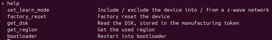
There we go:
Does it work?
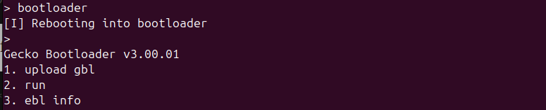
Yes, it does!
Let’s try to join a network with Z-Wave Long Range. Since we have no QR code or anything, let’s use the CLI to get the DSK, then generate a QR code using the Z-Wave JS Smart Start QR code tool:
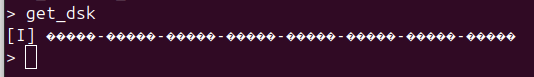
What. The. F…?
Don’t forget about the NVM
If you have a bit of Z-Wave knowledge, you might know that Z-Wave controllers store the network information in their non-volatile memory (NVM). End devices do, too. But because it can’t ever be easy, end devices use a slightly different area in their flash for this. We can look into the .map files the linker generates when building our controller and end device firmwares. Those files contain a lot of information we don’t need, and then this near the end:
Controller firmware
0x0807e000   linker_nvm_end = __main_flash_end__
0x08074000   linker_nvm_begin = (linker_nvm_end - SIZEOF (.nvm))
End device firmware
0x0807e000   linker_nvm_end = __main_flash_end__
0x08076000   linker_nvm_begin = (linker_nvm_end - SIZEOF (.nvm))
The flash page size on our hardware is 8192 bytes (0x2000), which means the end device firmware uses one less flash page (32 KiB total) than the controller firmware (40 KiB total) and starts one page later. The end device firmware using one less page will confuse the heck out of the wear leveling algorithm when we switch back to the controller. End device and controller firmwares also use different keys to identify objects in the NVM, so we can’t just continue as if nothing happened.
So, let’s just erase it when switching. Unfortunately this means we’ll have to resort to NVM backups, but that’s fine.
So, I added a new command to the bootloader
    "1. upload gbl\r\n"
    "2. run\r\n"
    "3. ebl info\r\n"
+   "4. erase nvm\r\n"
    "BL > ";
with a confirmation to avoid accidental erasures. After confirming, the bootloader will now erase all NVM pages. The empty page before the end device NVM isn’t actually used, so we just erase it anyways:
// snip ✂️
case ERASE_NVM:
  // Erase NVM
  // The address and size can be determined from the .map files after firmware compilation.
  // Right now, those are either:
  // - Controller 0x08074000
  // - End device 0x08076000
  // ...which both end at address 0x0807dfff
  uint32_t nvm_address = 0x08074000;
  uint32_t nvm_size = 0x0000c000;
  // Erase all pages that start inside the write range
  for (uint32_t pageAddress = nvm_address & ~(FLASH_PAGE_SIZE - 1UL);
    pageAddress < (nvm_address + nvm_size);
    pageAddress += FLASH_PAGE_SIZE) {
    flash_erasePage(pageAddress);
  }
  char str[] = "\r\nNVM erased\r\n";
  uart_sendBuffer((uint8_t *)str, sizeof(str), true);
  // [...]
  break;
Start the firmware again, aaaaand… 🥁🥁🥁

Success?

Tokens?
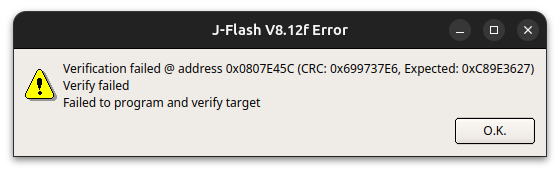
For a while, I did actually think that was it. The bootloader was done. But then I tried switching back to the controller firmware and was immediately greeted with this very descriptive message from the bootloader:
Bootloader error 0x44
A bit of digging in the SDK sources reveals that is a parser error BOOTLOADER_ERROR_PARSER_UNKNOWN_TAG. But why? I used the same gbl file I had previously uploaded to the device and it worked just fine.
gbl files contain multiple sections, called tags, which contain information about the firmware version, etc., and the firmware image itself. These tags can be encrypted (and signed), to ensure that only the device they are intended for can decrypt them - or someone really dedicated with the right tools:
Encrypting the firmware image has multiple reasons. A big one is hiding “proprietary” firmware from competitors - but just with locks, this just keeps honest people out! However it also prevents end users from accidentally installing incompatible firmware. The latter is the reason we’ll also be encrypting and signing our firmware, but we’ll make the keys open source!
Those encryption and signing keys, along with some other things (all commonly called tokens) are stored in a special page in the device’s flash memory. They are uploaded during initial programming
commander flash --tokengroup znet --tokenfile vendor_encrypt.key --tokenfile vendor_sign.key-tokens.txt
It just so happens that the page used for token storage comes just after the NVM pages:

And if you look at the code listing above really, really closely, you might spot a bug!
uint32_t nvm_address = 0x08074000;
uint32_t nvm_size = 0x0000c000;
0x08074000 + 0x0000c000 is not 0x0807dfff, but 0x0807ffff! We’re erasing the token storage. This means I just locked myself out, because the encrypted GBL files no longer match the encryption keys on the device, which are now all 0xffff...ffff.
So, let’s fix that.
  uint32_t nvm_address = 0x08074000;
- uint32_t nvm_size = 0x0000c000;
+ uint32_t nvm_size = 0x0000a000;
Flash everything again, switch to end device firmware, erase the NVM, and finally join our device…
Aaaaaaargh!
Digging deeper
Now, a long debugging session followed. I started by erasing everything, and flashing the bootloader, then dumped the entire flash. Uploaded tokens, dumped the entire flash. Uploaded a controller firmware, dumped the entire flash. Switched to end device firmware, dumped the flash. Erased NVM, dumped the flash, etc…
I then compared everything to figure out when, where and how the flash contents changed. I learned a lot from this.
The EFR32ZG23AxxxF512 chip that we use contains two flash regions:
- Main Flash: address
0x0800_0000, size 512 KiB - User data: address
0x0FE0_0000, size 1 KiB
The GBL encryption key (16 bytes) is placed in the memory region 0x0807e286 ... 0x0807e295. Addresses 0x0807e34c ... 0x0807e38b (64 bytes) contain the private part of the signing key.
The user data area seemed to be unused by the controller firmware, but after starting the end device firmware, there was a single 0x0b written to address 0x0fe0_0074. More on this later.
The firmware image gets stored in the main flash at address 0x0800_6000. This isn’t very interesting for our purposes. After starting the firmware image, I spotted NVM page headers (I know how they look like because of nvmedit) at addresses 0x0807_4000 (controller only), 0x0807_6000, … until 0x0807_c000.
The controller firmware also creates empty NVM pages at addresses 0x0806_e000, 0x0807_0000 and 0x0807_2000. I can only assume that someone at Silabs forgot to update the initialization code after reducing the NVM size from 64 KiB to 48 KiB (and later 40 KiB) in the 800 series firmwares…
Address 0x0807e3e0...0x0807e3ff contain some random data, which turns out to be the public key of our end device:
0007e3e0: 6747 1c12 7f8d 5508 1e3c 6ba8 680e 103d  gG....U..<k.h..=
0007e3f0: 76ca 28f4 5630 d1de acb2 0586 ebba e95f  v.(.V0........._
The first 16 bytes are the device-specific key (in this case 26439-07186-32653-21768-07740-27560-26638-04157), the other 16 are the rest of the public key that the user never sees.
Addresses 0x0807e400 ... 0x0807e459 contain something that looks suspiciously like the QR code
0807e400: 3930 3031 3132 3038 3430 3033 3037 3230  9001120840030720
0807e410: 3534 3036 3138 3430 3836 3031 3436 3237  5406184086014627
0807e420: 3231 3231 3530 3738 3738 3338 3536 3530  2121507878385650
0807e430: 3233 3432 3030 3130 3034 3335 3430 3135  2342001004354015
0807e440: 3336 3032 3230 3031 3132 3630 3030 3031  3602200112600001
0807e450: 3030 3030 3130 3235 3833 FFFF 00FF FFFF  0000102583ÿÿ.ÿÿÿ
0807e460: 3038 3033 3030 3300 0000 0000 0000 0000  0803003.........
but then there’s a random FFFF 00FF FFFF in the middle that does not make sense.
Earlier, I had found some headers files with definitions for the tokens and functions to read them, like ZW_GetMfgTokenData, but Silicon Labs have helpfully hidden the implementation in their pre-compiled binaries they ship with the SDK.
All code is open source if you can read assembly
I can’t read assembly though, so it was time for Ghidra! This way I just had to try and understand some terrible decompiled C code instead.
This helped me understand the rest of what’s going on - or so I thought.
The lone 0x0b in the user data area is the region token (here EU Long Range). When the region in the Serial API is set to Default, this value is used instead. Manufacturers can use this to use a single firmware for multiple regions.
The 0x00 in the middle of the random FFFF 00FF FFFF in the QR code is used as a flag to indicate whether the QR code etc. has been initialized. The end device firmware sets this to 0 on first startup. For some reason it wouldn’t do this after switching from a controller firmware though.
The QR code seems to has grown since its first inception. It consists of 90 bytes at address 0x0807_e400 and up to 16 more bytes at address 0x0807_e460, with the ready flag inbetween. The part about the DSK we figured out above is correct. There are also another 32 bytes in front of it that can contain a private key.
Great, so let’s use a debugger and set the ready flag back to 0xff, so the initialization code runs again.
Flash page locking is a thing, apparently
Looking at the decompiled code again, the initialization code also enables write protection on the entire flash page. So after it has run, we can’t change the flag anymore.
The EFR32xG23 reference manual helpfully explains that the Memory System Controller (MSC) on our chip is responsible for protecting memory and that the MSC_PAGELOCK1 register can be used to lock/unlock pages. But it also mentions that we won’t be able to unlock the page once it has been locked:
Host is only allowed to write 1. Root and Debug are allowed to clear this register.
We are Host… What now?
The obvious, and easy solution would be having the controller firmware write a QR code on first startup as well, even if it doesn’t use it. However, that functionality is also hidden in Silabs’ pre-compiled binaries, because why make something open source that somebody might want to use?! And I’m not particularly keen on cleaning up the messy C code Ghidra spits out.
Going nuclear
Taking one step back, we were able to erase the token storage page, although the reference manual states that flash page locking prevents erasing. It seems we just cannot write to it after the firmware has locked it.
So what we do now, is read all tokens (that we know about), then erase the NVM and the token storage page (it’s now a feature, not a bug), and then write the tokens back. The ready flag only gets set if the QR code we read before is valid (i.e. does not start with 0xff).
We just need to take care of the alignment of the data we write. The flash used on our chip requires 4-byte aligned writes with data whose length is a multiple of 4. But for some odd reason some of the tokens are stored 2-byte aligned or have a length that’s just a multiple of 2, not 4.
// snip ✂️
case ERASE_NVM:
  // Erase NVM
  // The address and size can be determined from the .map files after firmware compilation.
  // Right now, those are either:
  // - Controller 0x08074000, size 0xa000
  // - End device 0x08076000, size 0x8000
  // ...which both end at address 0x0807dfff
  uint32_t nvm_address = 0x08074000;
  uint32_t nvm_size = 0x0000a000;
  uint32_t zpal_page_size = 0x00002000;

  // In the page at address 0x0807e000, ZPAL stores tokens like the encryption key,
  // but also the QR code, DSK, etc. The controller firmware does not generate the DSK,
  // and the end device firmware only does it when the byte at address 0x807e45c is 0xff.

  // For some reason, we can only erase that page, but not unlock it for resetting that byte.
  // Hence we read the tokens first, erase NVM and the ZPAL page, then restore the tokens

  // It would be much easier to just have the controller firmware also generate a DSK,
  // but Silabs hides this functionality in the end device binaries...

  uint32_t btl_enc_key_address = 0x0807e284; // Actually at 0x0807e286, but that's not 4-byte aligned
  uint8_t btl_enc_key_data[20]; // Actually 16 bytes, but we need to read 20 bytes to keep the alignment
  memcpy(btl_enc_key_data, (uint8_t *)btl_enc_key_address, sizeof(btl_enc_key_data));

  uint32_t btl_sign_key_address = 0x0807e34c;
  uint8_t btl_sign_key_data[64];
  memcpy(btl_sign_key_data, (uint8_t *)btl_sign_key_address, sizeof(btl_sign_key_data));

  uint32_t zpal_prk_address = 0x0807e3c0;
  uint8_t zpal_prk_data[32];
  memcpy(zpal_prk_data, (uint8_t *)zpal_prk_address, sizeof(zpal_prk_data));

  uint32_t zpal_puk_address = 0x0807e3e0;
  uint8_t zpal_puk_data[32];
  memcpy(zpal_puk_data, (uint8_t *)zpal_puk_address, sizeof(zpal_puk_data));

  uint32_t zpal_qr_address_1 = 0x0807e400;
  uint32_t zpal_qr_address_2 = 0x0807e460;
  uint8_t zpal_qr_data_1[92]; // actually 90, but that's not a multiple of 4
  uint8_t zpal_qr_data_2[16];
  memcpy(zpal_qr_data_1, (uint8_t *)zpal_qr_address_1, sizeof(zpal_qr_data_1));
  memcpy(zpal_qr_data_2, (uint8_t *)zpal_qr_address_2, sizeof(zpal_qr_data_2));

  // Erase all pages that start inside the write range
  for (uint32_t pageAddress = nvm_address & ~(FLASH_PAGE_SIZE - 1UL);
      pageAddress < (nvm_address + nvm_size + zpal_page_size);
      pageAddress += FLASH_PAGE_SIZE) {
    flash_erasePage(pageAddress);
  }

  // Write the tokens back to where they belong
  flash_writeBuffer(btl_enc_key_address, btl_enc_key_data, sizeof(btl_enc_key_data));
  flash_writeBuffer(btl_sign_key_address, btl_sign_key_data, sizeof(btl_sign_key_data));
  flash_writeBuffer(zpal_prk_address, zpal_prk_data, sizeof(zpal_prk_data));
  flash_writeBuffer(zpal_puk_address, zpal_puk_data, sizeof(zpal_puk_data));
  flash_writeBuffer(zpal_qr_address_1, zpal_qr_data_1, sizeof(zpal_qr_data_1));
  flash_writeBuffer(zpal_qr_address_2, zpal_qr_data_2, sizeof(zpal_qr_data_2));

  // To avoid re-initializing the QR code every time, also set the ready flag if we have a non-empty QR code
  if (zpal_qr_data_1[0] != 0xff) {
    uint32_t qr_ready_address = 0x807e45c;
      // Needs to be 4-byte aligned
    uint8_t qr_ready_data[4] = {0, 0xff, 0xff, 0xff};
    flash_writeBuffer(qr_ready_address, qr_ready_data, sizeof(qr_ready_data));
  }

  char str[] = "\r\nNVM erased\r\n";
  uart_sendBuffer((uint8_t *)str, sizeof(str), true);

  // [...]
  break;
That’s it!

Yes, really. No catch this time. It works!
Just took way longer than I had expected…
Update 2025-02-22
Narrator: It did not, in fact, work…
It turns out that S2 bootstrapping such an end device would fails because it does not send its DSK to the controller.
Some further investigation revealed that some S2 related information is also stored in the NVM, in a format I couldn’t be arsed to reverse engineer yet. Luckily the fix is simple: Don’t try to preserve the public key, private key, or the QR code, just erase them. Although this causes the end device to generate new keys and a new QR code whenever the NVM is erased, but at least it can be included and works normally.
This shortens the above code a bit:
// snip ✂️
case ERASE_NVM:
  // Erase NVM
  // The address and size can be determined from the .map files after firmware compilation.
  // Right now, those are either:
  // - Controller 0x08074000, size 0xa000
  // - End device 0x08076000, size 0x8000
  // ...which both end at address 0x0807dfff
  uint32_t nvm_address = 0x08074000;
  uint32_t nvm_size = 0x0000a000;
  uint32_t zpal_page_size = 0x00002000;

  // In the page at address 0x0807e000, ZPAL stores tokens like the encryption key,
  // but also the QR code, DSK, etc. The controller firmware does not generate the DSK,
  // and the end device firmware only does it when the byte at address 0x807e45c is 0xff.

  // For some reason, we can only erase that page, but not unlock it for resetting that byte.
  // Hence we read the tokens first, erase NVM and the ZPAL page, then restore the tokens

  // It would be much easier to just have the controller firmware also generate a DSK,
  // but Silabs hides this functionality in the end device binaries...

  uint32_t btl_enc_key_address = 0x0807e284; // Actually at 0x0807e286, but that's not 4-byte aligned
  uint8_t btl_enc_key_data[20]; // Actually 16 bytes, but we need to read 20 bytes to keep the alignment
  memcpy(btl_enc_key_data, (uint8_t *)btl_enc_key_address, sizeof(btl_enc_key_data));

  uint32_t btl_sign_key_address = 0x0807e34c;
  uint8_t btl_sign_key_data[64];
  memcpy(btl_sign_key_data, (uint8_t *)btl_sign_key_address, sizeof(btl_sign_key_data));

  // Erase all pages that start inside the write range
  for (uint32_t pageAddress = nvm_address & ~(FLASH_PAGE_SIZE - 1UL);
      pageAddress < (nvm_address + nvm_size + zpal_page_size);
      pageAddress += FLASH_PAGE_SIZE) {
    flash_erasePage(pageAddress);
  }

  // Write the tokens back to where they belong
  flash_writeBuffer(btl_enc_key_address, btl_enc_key_data, sizeof(btl_enc_key_data));
  flash_writeBuffer(btl_sign_key_address, btl_sign_key_data, sizeof(btl_sign_key_data));

  char str[] = "\r\nNVM erased\r\n";
  uart_sendBuffer((uint8_t *)str, sizeof(str), true);

  // [...]
  break;
Now it really works, I promise!